Short answer questions:
Each of the following questions should be answerable in a few (1-3) sentences and/or a diagram. Point form answers are acceptable as long as they are clear. No calculations are required.
S1. The diagram shows wave fronts propagating outward from two sources. Indicate the path length differences at each of points A through D.
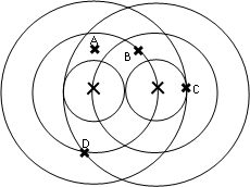
S2. For the figure in question S1 indicate below whether each of points A through D are locations of constructive or destructive interference.
A: constructive destructive
B: constructive destructive
C: constructive destructive
D: constructive destructive
S3. The diagram shows a very simple circuit. The power "in" the battery is Ie and the power "in" the resistor is I2R. A power always refers to a rate of conversion of one form of energy to another form. What energy conversion is occurring in the battery (from what form to what other form)? What energy conversion is occurring in the resistor?

S4. The photoelectric experiments are said to have demonstrated the particle nature of light. Name an observed phenomenon in the photoelectric effect experiments which could not be explained using the wave model of light. Describe what the wave model predicted and what was actually observed.
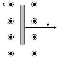
S5. The diagram shows a metal bar moving through a region in space with a magnetic field out of the page. Which end of the bar will be the higher potential end? Explain how you know.
S6. Below is a snapshot graph of two waves on a string approaching each other. On the axis provided sketch the snapshot of the string 2 seconds later.

S7. The diagram shows two charges, one positive and the other negative.
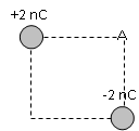
a) Indicate, roughly, the direction of the electric field at point A.
b) Indicate, roughly, the direction of the force on an electron placed at point A.
S8. Explain how you could charge two metal spheres so that they have charges of exactly equal magnitude but opposite sign. A sequence of charge diagrams might help your explanation.
S9. Light of wavelength 500 nm is passed through a diffraction grating with a distance between slits of 2100 nm. What is the maximum order (value of m) bright fringe that could be observed with this system? Explain how you know.
S10. A circuit containing a capacitor is shown. The switch is initially open and the capacitor is initially uncharged. Describe what happens to the voltage difference across the capacitor after the switch is closed. Explain.
Long Problems
Answers should be given to an appropriate number of significant figures.
P1. The diagram shows the end view of a solenoid. The solenoid has 4000 turns and is 10.0 cm long. Inside the solenoid is a square "loop" of copper, 1.00 cm on a side, which has a resistance of 0.0100 W. The inside loop is not connected to a battery or other voltage source. Initially, there is a 10.0 A current in the solenoid in the direction indicated. At t = 2.00 × 10⁻⁶ s the current starts to decrease at a uniform rate until, at 5.00 × 10⁻⁶ s, the current in the solenoid is 0 A. The current then remains zero.
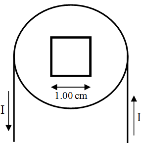
a) Find the strength of the magnetic field (magnitude and direction) inside the solenoid initially.
b) What is the initial magnetic flux through the inner loop? On the axes provided plot the magnetic flux through the inner loop as a function of time (be sure to label the axis and provide clear scales on the axes).
c) When does current flow in the inner loop? What is the direction of the current in the inner loop?
d) What is the magnitude of the current in the inner loop?
P2. A wire is attached to a rigid support at one end. The other end passes over a pulley and has a mass suspended from it as shown. The wire has a mass of 2.00 g.
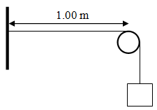
a) If a 10.0 kg mass is suspended from the wire then what is the wave speed on the wire?
b) If the wire is plucked it will vibrate at its fundamental frequency. What will the frequency of vibration of the wire be?
c) As any guitar playing physicist can tell you, if you touch the wire lightly at its center then you force there to be a node there (guitar players call this "playing harmonics"). What frequency will the wire vibrate at if you touch it in the center while plucking it?
e) Where would you need to touch the wire to force it to play its 3rd harmonic when plucked?
P3. The diagram shows the electrical equipotential curves in some region.
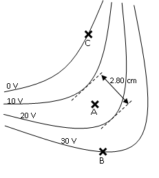
a) On the diagram, sketch the electric field lines in this region.
b) Use the information on the diagram to find the electric field strength at point A.
c) A proton is placed at point B. What is the electrical potential energy of the proton when it is at that point?
d) Suppose the proton is launched from point B with an initial speed of 4.90 × 10⁴ m/s. It is launched in a direction (we're not worried about the direction in this question) such that a short time later it passes through point C. What is the speed of the proton as it passes through point C?
e) On its way from point B to point C the proton passes through point A. What is the magnitude of the electric force on the proton as it passes through point A?
P4
b) Sketch a history graph for the point at 4.00 m. Be sure to label the axes and supply scales on the axes.
c) If the wave is represented as a sine function then what is the phase of the wave at x = 4.00 m at t = 2.00 s?
d) Write the displacement as a function of time and position, Dy(x, t), for this wave. Your expression should have numerical values, including units, for all quantities except x and t.
P5. The diagram shows part of two, long, parallel wires. The upper wire has a current of 20.0 A to the right.

a) What is the magnetic field (magnitude and direction), due to the top wire, at the location of the bottom wire?
b) Suppose we wish to magnetically levitate the bottom wire. What direction must the current in the bottom wire flow?
c) Suppose the portions of wire that are parallel are 5.00 m long and the bottom section of wire has a mass of 5.00 g. What magnitude of current needs to flow in the bottom wire for it to be levitated?
P6. In the circuit at right the switch is initially open. We want to measure the potential across the unknown battery but our voltmeter is broken. We know the resistance of resistor R1 to good precision from previous measurements. We do not know the resistance of R2 to sufficient precision to properly measure the potential across the battery. So first we'll measure the resistance of R2.
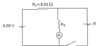
a) With the switch open the ammeter reads 1.00 A. What is the resistance of resistor R2 to an appropriate precision?
b) What is the potential difference across R2 when the switch is open?
c) When the switch is closed the ammeter reads 1.57 A. What is the potential difference across resistor R2 now?
d) What is the potential difference across the unknown battery?