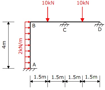
Question 1: The rigidly jointed frame shown in Figure has bending stiffnesses such that EIAB = 1000kNm2and EIBC = EICD = 1600kNm2.
A) Determine the joint rotations at B and C.
B) Hence, plot a bending moment diagram for the frame stating principal values.
C) Sketch a displaced shape for the frame.

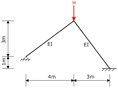
Question 2: Determine the critical load (Wcrit) to cause elastic instability of the rigidly jointed frame shown in figure below. The frame members have constant bending stiffnesses (EI) as indicated on the figure, where E is the modulus of elasticity and I is the second moment of area.

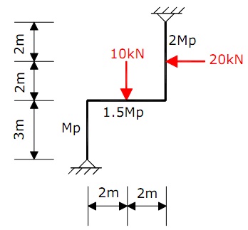
Question 3. For the collapse loads indicated in figure below, find the required plastic moment of resistance (Mp). The frame members have varying plastic moments of resistance as indicated on the figure.

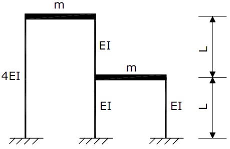
Question 4: The two-storey frame shown in Figure below is such that the self-mass may be considered to be located at the beam levels and the beams may be presumed to be rigid. The self-mass (m) at each beam level and column stifnesses (EI) are indicated on the figure, where E is the modulus of elasticity and I is the second moment of area. Determine the natural circular frequencies and natural modes of vibrations of the frame and provide sketches of these.
