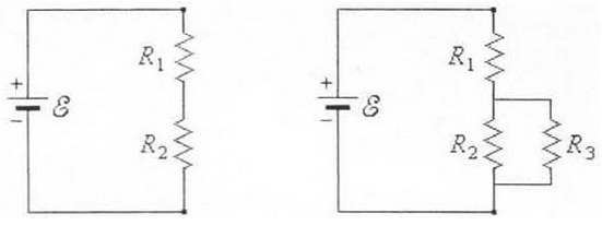
The left diagram below describes two resistors in series with an ideal battery, in the diagram on the right; a third resistor has been added in the parallel with R2. The three resistors show all have similar resistance of 5 ohms each. The emf is similar in both the diagrams and is 10 volts.
Q1. In which diagram is the current via R1 more? (Choose the correct one)
a) LEFT
b) RIGHT
c) BOTH THE SAME
Q2. In which diagram is the magnitude of potential difference across R2 is more?
a) LEFT
b) RIGHT
c) BOTH THE SAME
Regarding the diagram on the right, compute the current via R3 (Show all of your work and reasoning to get the full credit).