Introduction
The objective of Part I is to propose a feasible design of a microscale device (“microdevice”) that allows tensile tests to be performed on specimens only several hundred nanometers in diameter (“nanowires”). The basics of this design are provided to you. These basics are conceptually the same as those that have been used in research laboratories to perform tensile tests on nickel nanowires1,2. Those laboratories have performed detailed, in--depth design calculations of a more complicated microdevice (Figure A) using more advanced topics than are covered in ME 305; however, use of more introductory topics can still lead to a firm understanding of this microdevice’s design. This project focuses only on the design of a simplified version of the microdevice, shown in Figure B.
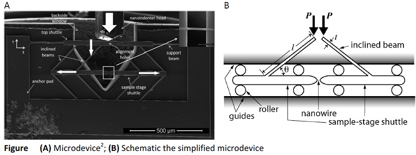
Description of the Simplified Microdevice
• The microdevice is designed to be mounted beneath a nanoindenter and to convert the downward movement of the nanoindenter tip into 2--D movement of the sample--stage shuttle. The movement of the two halves of the sample--stage shuttle in opposite, horizontal directions effects uniaxial tensile loading of a horizontally oriented specimen mounted across the gap of the sample--stage shuttle.
• The microdevice is made entirely of single--crystal silicon: E = 160 GPa; ν = 0.278; σfracture = 7000 MPa when no flaws are present; σfracture = 210 MPa when flaws are present. Silicon is a linear--elastic, brittle material.
• For the purposes of this course project, the specifics of the top shuttle (Figure A) are not of concern. You are to assume that, effectively, the top ends of the two inclined beams are loaded directly, each by a force P equal to one half of the force applied by the nanoindenter tip (Figure B). Moreover, you are to assume that P is a translating “follower load”, meaning that P is always acting downward on the top end of the beam, no matter how that end translates as a result of beam deflection, beam deformation, sample--stage translation, etc.
• The thickness of the sample--stage shuttle can be considered large enough so that any deflection and deformation of this element can be considered negligible. Note that the sample--stage shuttle and inclined beams are fabricated as a single unit, so there are no pin joints or otherwise moveable joints connecting the inclined beams to the sample--stage shuttle. The rollers and guides are assumed to be rigid and frictionless.
Design Tasks
The focus of your design considerations is on the two inclined beams that connect the sample stage to the top stage and base. The beams are square in cross--section. Your team is to propose a thickness (t), length (l), and incline angle (θ ) of these beams that permit the following conditions:
- A tensile displacement of up to 800 nm, at a resolution of 1 nm, can be applied to the sample.
- A tensile force of up to 0.1 mN, at resolution of 70 nN, can be applied to the sample.
- The micro device can be operated with a nanoindenter that has a force resolution of 70 nN, a displacement resolution of 0.8675 nm, a maximum allowable force of 1mN, and a maximum allowable displacement of 5000 nm.
Deliverables
One concise and complete report is required for each team (2 people/team). The report must consist of the following sections:
a) Cover Page: Include your name, course number (ME305), section (A1), and date.
b) Introduction: This section should summarize the objective and your overall approach.
c) Methods: This section should include an organized and logical description of your design process and the methods by which you determined if a candidate design met the objectives.
d) Results: This section should include a set of figures that presents your final design and the results of calculations that demonstrate, in theory, that your design meets all components of the objective.
e) References: This section should include a list of any references consulted when working on this project. for bibliographic reference material, full citations should be provided.
f) Appendix: This section must include final versions of any computer code written for this project. In addition, include any other material that you think is directly relevant to presenting your design process and results. The combined length of the Introduction, Methods, and Results should be no more than seven double--space pages (12--pt font, 1” margins), inclusive of all figures and tables.