Task 1
Use computer-aided design software to produce a design drawing or scheme.
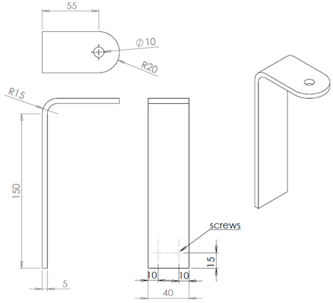
1. A model of a bracket is shown in the figure 1. The beam material is 2014 Aluminium alloy. It is subjected to a downward vertical force of 14kN applied through a cylindrical pin (not shown) in a hole near its upper end. The bottom of the beam can be fixed either by fixing the end or using two screws with holes drilled at the places indicated.
a. Produce a model of the beam using Solidworks or other suitable CAD software.
b. Analyse the stress applied on the beam due to the applied force for both types of fixtures. Based on the analysis make a suggestion as to what fixture to use. If neither of the fixing methods is sufficient to carry the load suggest a modification to the design with an explanation of why you have suggested it.
Produce screen printouts of your model and stress analysis showing all the details as evidence. CAD files should be ready to submit if required.

Figure 1 - Model of the Bracket.
Task 1 Learning Outcome
Explain the key features of a computer-aided design system.
1. Consider the use of computer-aided design systems in the product design process. Based on this and on your experience in using a 2D design and 3D modelling system, explain its key features. Use examples to demonstrate your familiarity with the software. These should include the feature below.
• Accessing standards
• Parts and material storage and retrieval
• Engineering calculations
• Integrated circuit design
• Circuit and logic simulation-including AC, DC and transient analysis
• Schematic capture
Task 3 Learning Outcome
Evaluate software that can assist the design process.
1. Evaluate the software that you have used in your design modelling. Your evaluation should consider the following and presented in a report.
• Costs associated with the software
• Compatibility with other software and technology used. E.g. CNC machining and rapid prototyping
• Functional as well as technical capability of the software when used in product design process.