Questions:
Industrial Application Images
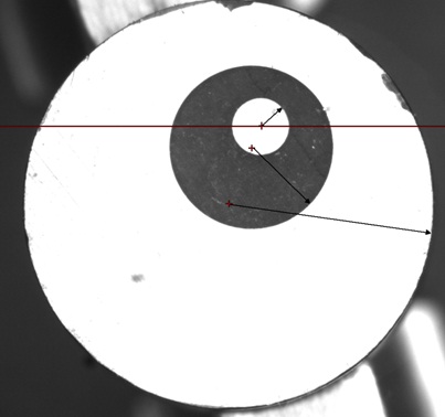
The two images below shows one of our attempts to come up with the rotation angle required. I believe that it does not work because we are using first order trig which assumes symmetry . Please comment on this assumption and or why it does not work. See attachment
To Whom It May Concern:
Description of Problem #1:
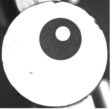
These are images of a manufactured part that goes into airbags. The entire part is called a header and consists of just the outer circular object- not the upper and lower clamps. The images are acquired via a vision system with a resolution of 1280 X 1024 pixels. The outer circle (header) is approximately 0.29" diameter. The most inside circle (white) is called the Pin, and the dark circle is called the Glass.
As you can see, the circles are not symmetrical to one another. At a processing station downstream, we need to weld a very small wire across the glass (dark area) from the Pin (inside circle) to the header (outside circle) . The weld is to be located just inside and just outside of the glass. This is referred to as the substrate length (A1) and is a specified dimension. The diagram below shows a header in its initial state (ie the initial vision snapshot). The black marks at the outside edge are actually marks I made to help confirm the rotations I made during testing of nonworking equations and do not exist on regular parts.

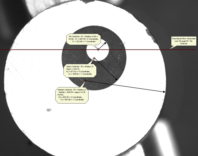
The need is to develop an equation to solve for degrees of rotation required to rotate the header (the point of rotation is the centroid of the header) so that the substrate length of 95.51 Pixels just covers the glass area. In the image below, the centroid and radius of the Pin (R1), Glass (R2), and Header (R3) are shown. Additionally, the red line represents a theoretical wire drawn through the Pin Centroid Y coordinate (Y1).
We want to solve for the degrees of rotation to rotate the header (clockwise as positive or counterclockwise as negative) to have the distance at the theoretical wire be equal to the substrate length (A) of our specified dimension. Again, after rotation, the theoretical wire is drawn through the Pin Centroid Y coordinate (Y1). As you know, after rotation, the theoretical wire will shift up or down as the circles are not symmetrical to one another. If the equation cannot be solved for exactly the future Y1 position, we want it to be as close as possible to the future Y1 Position.
A second snapshot is taken after rotation in order to make fine adjustments to the weld head at the downstream station. The equations we have come up with solve for this final adjustment of the weld tips.

The two images below shows one of our attempts to come up with the rotation angle required. I believe that it does not work because we are using first order trig which assumes symmetry . Please comment on this assumption and or why it does not work.

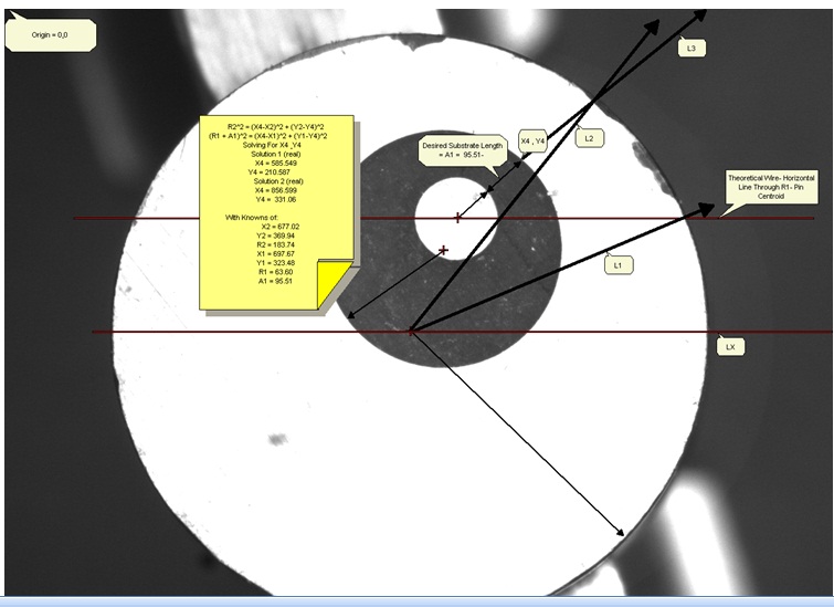
The image below shows the equation I used to come up with X4 , Y4. Please provide the actual equation to me using the known variables R1, X1, Y1, R2, X2, Y2, A1 . I was using WebMathematica to solve this equation and it times out before providing the solution when the variables are used as opposed to the actual values.
Upon experimentation, when I used the vision system to measure the distance across the Glass at an angle from P1 Centroid to the X4, Y4 position (ie before rotation), it is exactly equal to the desired substrate length.
After finding X4, Y4 , I thought to extrapolate that line (L3) past the outside of the header. The degrees of rotation desired (Theta_Rot) = Theta2 - Theta1 where Theta1 is the initial angle and Theta2 is the intersecting angle of L2 and L3. Theta1 is between LX and L1. Theta2 is between LX and L2.

Description of Problem #2:
Problem #2 is similar to problem#1 above except the the wire is NOT theorectical. It exists and is fixtured above the header. The header rotates just as above but the wire remains in the same location. In other words, the Header rotates under the wire. We need to rotate the header to a location under the wire such that the substrate length across the glass between the Pin and Header equals the Substrate length. We need to solve for the angle of rotation. The image below shows this setup. The wire is a very faint grey color. Ideally, the wire would be located as close to the Pin centroid as possible but as long as the wire is within the Pin area, that will suffice- given a workable distance from the top & bottom.