The purpose of the project is to perform a kinematic analysis of the web cutting mechanism shown below:
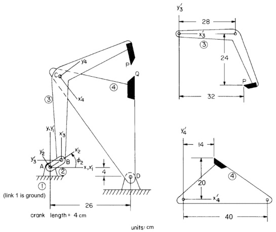
The model has 4 bodies: ground, a crank, a knife arm, and a rocker arm. Points of interest P and Q are defined on the tip of the cutting blades. The x velocities of these points are of particular interest. In an actual mechanism, a sheet of fabric or metal is fed between the blades and the blade tips come together periodically to slice off a section of the web. The machine is designed such that the x velocity of the blade tips matches very closely the velocity of the web. This allows for a clean cut, with little or no tearing. The crank is driven with an angular velocity of 100 rpm.
Complete the following and answer the questions:
Part A:
i. Construct a MotionView/MotionSolve model of the mechanism and solve for a minimum of 1 revolution of the crank. Select your joints such that your model is not over-constrained in 3-D and MotionSolve does not have to remove any constraints. Create body geometry that visually resembles the shapes of the bodies. You may use whatever form of SI units is convenient (cm, mm, m). You will likely need to refer to the trunk lid tutorial and/or the Altair reference document: Practical Aspects of Multi-Body Simulation with HyperWorks, which was provided on D2L.
ii. Indicate what types of joints you used and the total DOF of the mechanism.
iii. Plot the following (2 curves on each plot):
a. xP and xQ versus the crank angle
b. x.P and x.Q versus the crank angle
c. yP and yQ versus the crank angle
d. y.P and y.Q versus the crank angle
iv. Using the plots, determine the crank angle at which cutting occurs. Indicate these locations on the plot.
v. What should be the velocity of the web material as it feeds through the mechanism and why?
vi. Monitor how close the x positions of points P and Q agree throughout the simulation. If there is a crank angle interval over which xP and xQ differ, discuss this position difference concerning yP and yQ . Suggest any design changes that may be necessary (but do not carry them out).
Part B:
i. In MATLAB, utilize planar equations and the Method of Appended Driving Constraints to simulate the mechanism for a minimum of 1 revolution of the crank. Use your own Newton-Raphson iterative code to solve the position equations Use MATLAB’s nonlinear equation solver function, fsolve to solve the position equations. Create a separate MATLAB script that plot your step ii. simulation results post-solve.
ii. Repeat steps iii & iv from Part A using the results of your Part B simulation.
iii. Discuss any differences or similarities between your simulation results and the MotionView/MotionSolve results. Indicate why you think these differences exist.