Question 1: Sketch the water surface profiles for the cases below. Label the normal and critical depth lines as well as all of the water surface profiles.
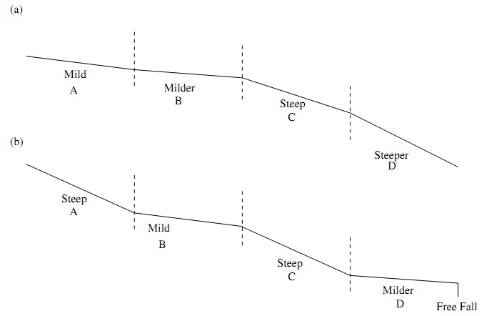
In part (b), the conjugate depth of the normal depth in channel section A is greater than the normal depth in section B. The conjugate depth of the normal depth in section C is less than the normal depth in section D.
Question 2: An early horizontal,12ft wide rectangular channel carries 60 cfs at a depth of 3.0 ft. The width of the channel is smoothly contracted to 6 ft at the downstream section.
(a) Determine if the flow will choke and both the downstream and upstream water depths.
(b) If there is also a 1 ft high step up in bottom elevation at the contraction, determine if the flow will choke and both the downstream and upstream water depths.
Question 3: A rectangular channel of width 12fth as an upstream slope of 0.02ft/ft and a downstream slope of 0.0005 ft/ft. Both reaches have lengths of 500 ft. The upstream reach has a Manning’s roughness of 0.016 and the downstream reach has a roughness of 0.011. The design discharge is Q = 460cfs, the low flow discharge is Q = 230cfs, and the flood discharge is Q = 690cfs.
a) Using the direct step method by hand with 1 step, determine the location of the hydraulic jump relative to the slope break for the design discharge. Classify the jump type and calculate the energy lost.
b) Design an Excel spreadsheet to calculate the location of the hydraulic jump relative to the slope break using a depth step size of 0.01 ft for the design discharge. All lengths and water depths must be accurate to 2 decimal places. Plot the water surface profile relative to the slope break.
Question 4: In HEC-RAS, model this system as 1 reach with cross-sections every 2 ft. For all 3 discharges (labeled as: design, low, flood),
a) Determine the water depths 10 ft from the upstream and downstream boundaries.
b) Determine the location of the hydraulic jumps (in ft from the slope break).
c) Output the water surface profile plots with all 3 discharges, including the water surface, energy grade line, and critical depth line.
Question 5: Consider a trapezoidal channel with a bottom width of 4 m, side slopes of 3:1 (H:V), and a bottom slope of 0.002 that carries 50 cms. The channel has a Manning’s roughness of 0.034.
a) Using the standard step method, determine the water depth 40 m up-stream of a location with a depth of 2 m.
b) Design an Excel spreadsheet to calculate the following reach steps. All lengths and water depths must be accurate to 2 decimal places.
Plot the water surface profile.
Question 6: For the model of Fall River and Butte Creek (Chapter 4 in the User Manual) in HEC-RAS,
a) Output the cross-section of all three Flood events for station 9.8 on one figure. Include only the water surface and energy grade line.
b) Output the profile of Butte Creek and the Lower Reach of the Fall River for all events on one figure. Include only the water surface and energy grade line.
c) Output the three dimensional view of the water surface profile the 50 year flood. Use a rotation angle of 25 degrees and an azimuthal angle of 30 degrees.