Assignment:
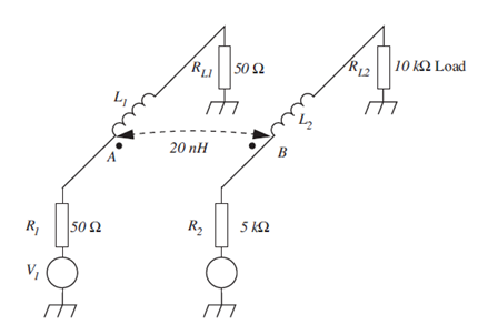
The mutual inductance between the two circuits shown in FIGURE is 20 nH. It may be assumed that (R1 + RL1) »ωL1 and that (R2 + RL2) » ail.
(a) Estimate the crosstalk voltage at the load of circuit B when the signal source of circuit A is V1 = 100 mV at 1 GHz.
(b) Plot the crosstalk voltage (at the load of circuit B) as a function of frequency.
(c) Suggest three ways of reducing inductive crosstalk.