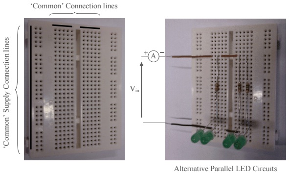
Aim: To gain experience implementing electronic circuits on breadboard, performing measurements and an appreciation for the operation of an LED.
Equipment:
1 – Breadboard
1 – 0 to 30V Variable DC Power Supply
1 - Multimeter

Laboratory Procedure:
Using a basic Green LED where:

Test 1: Forward Bias Operation
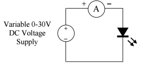
Connect the variable voltage supply to the LED as shown in the circuit below and determine the forward voltage at which 20mA flows through the diode by carefully increasing the supply voltage from 0V. Do not exceed 5V supply !

Test 2: Fixed Supply Usage
Using a 5V fixed input supply ( to replace the 30V variable supply) in the above circuit
i) Quickly place the LED across the supply and note its current/intensity/colour
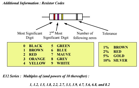
ii) Using your values for Test 1 calculate a suitable series resistor for use with this supply. Determine the nearest fixed resistor and implement the solution and confirm the resultant current flow.
Test 3: Series Operation
Repeat Test 2(i) for :
i) 2 series LED’s in the circuit.
ii) 3 series LED’s.
Test 4: Parallel Operation
Repeat Test 2(ii) for :
i) 2 Parallel LED’s in the circuit.
ii) 3 Parallel LED’s.
Results and Conclusions:
Each individual student should submit a written report which contains your results to the above tests and the following questions.Your conclusions should comment upon these results and any other findings you found during the laboratory exercise. Remember to support your findings theoretically and include reference support wherever possible.
Design the following circuits if all LED’s are to operate at 20mA and the circuits are to produce maximum intensity :
i) A series LED circuit from a 10V DC Supply
ii) A parallel LED circuit that requires <0.09A from a 5V DC supply
