Discuss the below in detail:
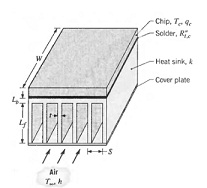
Q: An isothermal silicon chip of width W = 20 mm on a side is soldered to an aluminum heat sink (k = 180 W/m · K) of equivalent width. The heat sink has a base thickness of Lb = 3 mm and an array of rectangular fins, each of length Lf = 15 mm. Air flow at T8 = 20°C is maintained through channels formed by the fins and a cover plate, and for a convection coefficient of h = 100 W/m 2 · K, a minimum fin spacing of 1.8 mm is dictated by limitations on the flow pressure drop. The solder joint has a thermal resistance of Rt,c = 2 X 10- 6 m2 · K1W.
(a) Consider limitations for which the array has N = 11 fins, in which case values of the fin thickness t = 0.182 mm and pitch S = 1.982 mm are obtained from the requirements that W = (N - 1)S + t and S - t = 1.8 mm. If the maximum allowable chip temperature is Tc = 85°C, what is the corresponding value of the chip power qc? An adiabatic fin tip condition may be assumed, and air flow along the outer surfaces of the heat sink may be assumed to provide a convection coefficient equivalent to that associated with air flow through the channels.
(b) With (S - t) and h fixed at 1.8 mm and 100 W/m · K, respectively, explore the effect of increasing the fin thickness by reducing the number of fins. With N = 11 and S - t fixed at 1.8 mm, but relaxation of the constraint on the pressure drop, explore the effect of increasing the air flow, and hence the convection coefficient.
