Assignment:
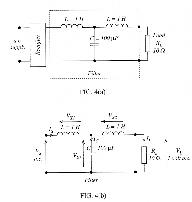
Figure (a) shows the circuit of a resistive load fed from a rectifier, via a filter. The filter is designed to remove unwanted a.c. that might be present in the output of the rectifier.
To test the performance of the filter, a 50 Hz alternating supply was connected directly to its input, as shown in Figure(b). The resulting a.c. voltage appearing across the load was then measured.
(a) Sketch a phasor diagram for a circuit of Figure(b) (Hint: begin at the output and work back towards the input.)
(b) Estimate the magnitude of the a.c. input voltage required to give a voltage of 1 V across RL.
(Hint: show that I xL21 »RL and therefore that the entire circuit can be regarded as reactive.)
