Assignment:
Question 1. Figure represents the equivalent circuit of a voltage regulator where an unregulated 12V source is used to provide a stabilised voltage Vout using an 8V zener diode.
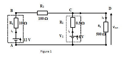
Using Kirchhoff’s voltage law and by writing the appropriate equations find:
i. The currents i2 & i3.
ii. The output voltage Vout.
iii. The power dissipated by the zener diode (resistor RZ).
Question 2. A p.d. of V is connected between terminals A and B of the network below For a frequency of 32.274861 kHz calculate :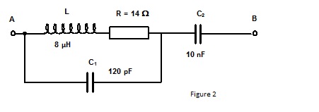
a. The j notation impedance of the network.
b. The polar representation of the impedance in the form R ∠Θ giving the answer as a positive angle.
c. The magnitude of the voltage across C2 and its phase relative to the supply voltage.