Question 1: Design and draw a circuit by using cascade system to operate two cylinders A and B which, on the operation of a start valve, produces the sequence A – B + B – A+. The cylinders must park in the positions B – A + when the start switch is in the ‘off’ position.
Question 2: Modify the circuit designed for question above to give an emergency stop which will park both cylinders in the extended position (that is, A + B +).
Question 3: Modify the circuit designed for question above to provide a failsafe. The fail safe must:
a) Act in the event of a decreased pressure at inlet to the group selecting valve.
b) Park the cylinders in the retracted position.
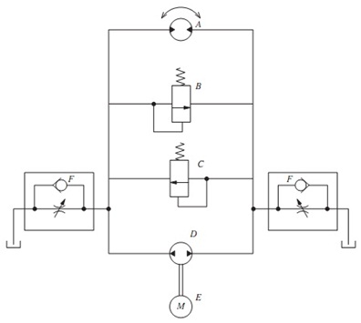
Question 4: Figure shown below is a hydraulic circuit.
a) State the name and aim of the components shown in the circuit diagram.
b) Describe the operation of this circuit.
c) Describe the limitations of this circuit in terms of ‘speed control’.
Question 5: Modify the design of the circuit illustrated in figure above and draw a circuit diagram to give rotary actuation in both directions by using a single direction pump (to replace the bi-directional pump) and giving a means of preventing over-speeding in the case of an overhauling load in both the directions.