Questions:
Question-1
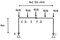
The following diagram shows a three pin frame loaded with 6kN roof dead loads at each purlin. The frame has pins at A, E and I. The knee joints at C and G are rigid joints (that is they are capable of transferring bending moments).
Determine the support reactions at the pin joints A, E and I for the following three pin frame and determine the bending moment at the knees at C and at G. Also determine the shear in the horizontal beams just next to the knee joints. Place half the 4kN load at E on each side of the hinge at E.

Question-2
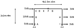
The following diagram shows the same three pin frame analysed in the previous workbook question and in the earlier worked example.
The load case shown in the diagram includes only the sideways wind loads applied to the building. (The same sideways loads were analysed in the earlier worked example but that load case included uplift on the roof, this load case does not include uplift.
As before, the frame has pins at A, D and G. The knee joints at B and F are rigid joints (that is they are capable of transferring bending moments).
Determine the support reactions at the pin joints A, D and G for the following three pin frame and determine the bending moment at the knees at C and at F. Also determine the shear in the horizontal beams just next to the knee joints
