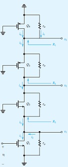
Response to the following problem:
The purpose of this problem is to investigate the signal currents and voltages at various points throughout a cascade

Amplifier circuit. Knowledge of this signal distribution is very useful in designing the circuit so as to allow for the equired signal swings. Figure shows a CMOS cascode amplifier with all dc voltages replaced with signal grounds. As well, we have explicitly shown the resistance ro of each of the four transistors. For simplicity, we are assuming that the four transistors have the same gm and ro. The amplifier is fed with a signal vi.
(a) Determine R1, R2, and R3. Assume gmro1.
(b) Determine i1, i2, i3, i4, i5, i6, and i7, all in terms of vi. (Hint: Use the current-divider rule at the drain of Q1:
(c) Determine v1, v2, and v3, all in terms of vi .
(d) If vi is a 5-mV peak sine wave and gmro =20, sketch and clearly label the waveforms of v1, v2, and v3.