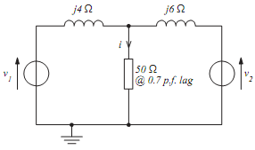
1. FIGURE 1 shows a 50 ? load being fed from two voltage sources via their associated reactances. Determine the current i flowing in the load by:
(a) applying Thevenin's theorem
(b) applying the superposition theorem
(c) by transforming the two voltage sources and their associated reactances into current sources (and thus form a pair of Norton generators).
v1 = √2 ×415cos(100Πt ) volts
v2 = √2 ×415sin (100Πt ) volts

FIG. 1
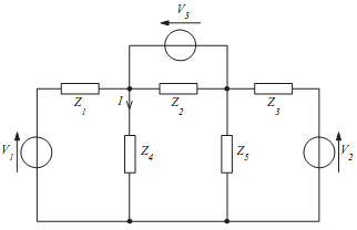
2. Determine, using the values given in TABLE A, the current I in the circuit of FIGURE 2 by:
(a) mesh analysis
(b) nodal analysis.

FIG 2
|
V1
|
120 ∠00 v
|
| V2 |
120 ∠900 v
|
|
V3
|
20 ∠450 v
|
|
Z1
|
2 Ω
|
|
Z2
|
-j 5 Ω
|
|
Z3
|
4 Ω
|
|
Z4
|
-j 5 Ω
|
|
Z5
|
j 4 Ω
|
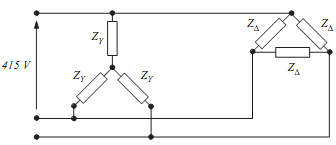
3. For the balanced three-phase loads shown in FIGURE 3,
ZY = (15 + j15) ? and
Z? = (45 + j45) ?. Determine:
(a) the equivalent single ?-connected load,
(b) the equivalent single Y-connected load obtained from the ?-Y transformation of (a) above,
(c) the equivalent single Y-connected load obtained by transforming the ? sub-load of FIGURE 3 to a Y and with the star-points of the two Y-sub-circuits connected together,
(d) the total power consumed in case (a) above if the line voltage of the three-phase supply is 415 V at 50 Hz.

FIG 3
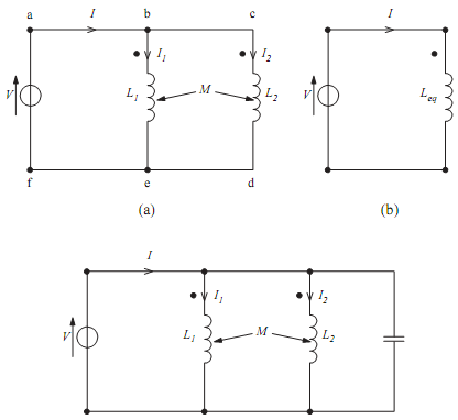
4. FIGURE 4(a) shows two inductances connected in parallel across an a.c. supply.
(a) Apply Kirchhoff's voltage law to loop abef and to loop abcdef of the circuit.
(b) Hence or otherwise obtain the current ratio I1/I2 in terms of the circuit inductances.
(c) See if you can show that L1 and L2 can be replaced by the equivalent inductor, Leq, of FIGURE 4(b) where
Leq = L1L2 - M2/L1 + L2 -2M
(d) A 1 nF capacitor is placed across the two inductors (FIGURE 4 (c)). If L1 = L2 = L and k = 0.5, determine the required value of L if the minimum current I flows from the supply when it is at a frequency of 1 MHz.

FIG 4
5. A 415V to 11 kV transformer has a rating of 200 kVA. The winding resistance and leakage reactance when referred to the primary are 0.014 ? and 0.057 ? respectively.
(a) Determine the % regulation of the transformer at 0.8 power factor lagging.
(b) In designing a particular 415V to 11 kV, 200 kVA transformer, the primary winding resistance is to be 10 m?. Find the maximum winding resistance of the secondary winding if the transformer is to have 2% regulation at unity power factor.