Discuss the below:
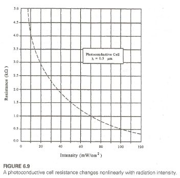
Q1. Design a system using the photoconductive cell in Figure 6.9 to measure and display light intensity. Make the design such that 20 to 100 mW/cm2 produces an output of .2 to 1.0 V. What is the readout error when the intensity is 60 mW/cm2?
Q2. A single silicon photovoltaic cell is found to have an open-circuit voltage of 0.6 V and a short-circuit current of 15 mA in full sunlight. Show how a collection of these cells can be arranged to deliver 500mW at 9.0V into a load. Write a verbal description of your solution.
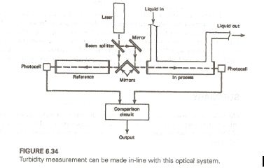
Q3. In a turbidity system such as that of Figure 6.34, the tanks are 2 m in length. A laser with a 2.2-mrad divergence, 2.1-mW power, and 1-mm exit radius is employed. If the sample nominally detracts from the beam power by 12% per meter, find the intensity of the beam at the detector. The laser is 1.5 m from the beam splitter. Note that the splitter halves the power and does not affect the divergence.
Q4. An automatic security camera must operate as follows when an intrusion occurs: 1. If the ambient light level is greater than 20mW/cm2, the shutter is activated. 2. If the ambient light is less than 20mW/cm2 a light source is triggered. 3. When the source lighting reaches 20mW/cm2, the shutter is triggered. Design the system and signal conditioning using the following assumptions:
a. The shutter and light source are triggered by TTL logic high signals.
b. A CdS cell with characteristics given in Figure 6.9 is used to monitor ambient light level.
c. A photodiode with the characteristics given will be used to measure light intensity after the light source is triggered. Explain why the CdS cell could not be used here also.