Question1) The cantilever beam-like structure shown in figure below is modelled using a 2 x 10 mesh of rectangular four-node plane stress elements of equal size. Geometric boundary conditions at x=0 are as follows: The horizontal displacement is zero where as the vertical displacement is zero only at y = 0. Do the following and compare with the beam theory solution.
(a) Construct the element matrix numerically using the 2x2 point rule.
(b) Construct the element load vectors and global load vectors.
(b) Plot vertical displacement along the y = 0 line.
(c) Plot stress values at element centroids.
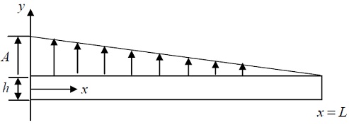
Py=A(1-X/L)lb/in
where A is a given constant value.
E=107psi v=0.3
L=10 in, h=1.0 in , Width (in the z direction) =0.4 in
Question2) The structure shown Problem 1 is subject to the temperature change given as ΔT=By where B is a given constant value. There is no applied surface load.
(a) Print out the global load vector due to the temperature change.
(b) Plot vertical displacement along the y = 0 line.
(c) Plot stress values at the element centroids.
Question3) Do again problem 2 with the additional constraint given as follows:
Vertical displacement is zero at x = L, y = 0.