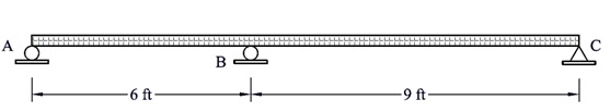
Problem 1:
Using force method, determine the reactions at supports A and C in the shown beam and draw the bending moment diagram. Point B is an intermediate hinge. EI is constant.
Problem 2:
Using force method, determine the reactions at supports A, B, and C in the shown beam and draw the bending moment diagram due to:
• Settlement of support B equal to 0.25 in.
• Temperature increase of 200 °F at the soffit of beam AB. (ΔT = 200 °F)
• Settlement of support B of 0.25 in. and settlement of support C of 0.625 in.
Take E = 29 × 103ksi, I = 500 in.4, Coefficient of thermal expansion α = 6 × 10⁻⁶ /°F
(Solve each case separately)
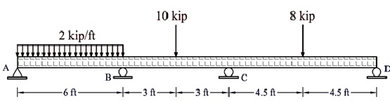
Problem 3:
Using force method, determine the reactions at supports A, B, C, and D for the shown continuous beam. Draw the final bending moment diagram due to the applied loads.
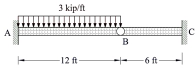
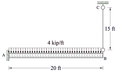
Problem 4:
The Cantilevered beam is supported at one end by a 0.5-in.-diameter suspended rod BC and fixed at the other end A. Determine the force in the rod due to a uniform loading of 4 kip/ft.
E = 29 × 103ksi for both the beam and the rod. IAB = 350 in.4
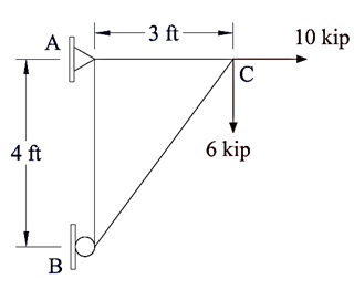
Problem 5:
Using stiffness method for truss analysis, determine the forces in the truss members shown in the figure. The support at A is a hinged support, while the support at B is a roller support. EA is constant for all truss members.