--%>

Problem related to mass flow rate

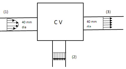
Water flows via a control volume as illustrated in the figure below. At Section (1) the diameter is 40 mm and the velocity profile is given by the V(r) = 10 (4 – r2) m/s, here r is the  distance from the centerline. At Section (2) the mass flow rate is 10 kg/s and at Section (3) the diameter is about 40 mm and the flow is uniform. Compute the uniform velocity at the section (3). The Density of water is taken as 1000 kg/m3

224_uniform velocity.jpg

   Related Questions in Mechanical Engineering

  • Q : Explain steam turbine diaphragm Steam

    Steam turbine diaphragm: Steam turbine includes of phases, number and size of the phases depends on the break horse-power of the turbine. The phase has set of moving and fixed blades. Moving blades are joined to th

  • Q : Arena Are you able to assist with these

    Are you able to assist with these two assignments in Arena simulation below? You can use the Basic Process instead of Blocks and Elements. An office of state license bureau has two types of arrivals. Individuals interested in purchasing new plates are characterized to have inter-arrival times dis

  • Q : Ergonomics in product design

    Ergonomics: This is concerned with how easy (comfort, complexity) the product is to use by the targeted market. Physical human dimensions must be considered when designing the driver's seating, instruments, and controls in a car. Slight variations bet

  • Q : Undamped single degree of freedom (a)

    (a) The response for an undamped single degree of freedom system under free vibration is given as where ωn is the natural frequency and A and B are unknown that can be determined from the initial conditions. The response 

  • Q : Brazing and Welding Differentiate the

    Differentiate the term Brazing and Welding?

  • Q : Difference between pressure vessel &

    Difference between pressure vessel & column: The Pressure vessels (cylinder or tank) are utilized to store fluids under pressure. If the pressure vessel are design in the form of column to separate the gas at u

  • Q : Unilateral and Bilateral Tolerance

    Explain difference between the Unilateral and Bilateral Tolerance?

  • Q : Problem on head loss The pump

    The pump illustrated in the figure adds 20 kW of power to the flowing water. The only vital loss is that which takes place across the filter at the inlet of the pump. Find out the head loss for this filter. Note that the gage pressure upstream of the filter is negativ

  • Q : Technology and Engineering Explain

    Explain difference between the Technology and Engineering?

  • Q : Describe Process Flow Diagram Process

    Process Flow Diagram: A Process Flow Diagram or System Flow Diagram exhibits the relationships among the main components in the system. It too has fundamental information regarding the material balance for the process.