--%>

Problem on mechanical efficiency of the pump

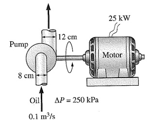
The oil pump is drawing 25 kW of electric power while pumping oil with ρ = 860 kg/m3 at a rate of 0.1 m3/s. The inlet and outlet diameters of the pipe are of 8 cm and 12 cm, respectively. When the pressure rise of oil in the pump is measured to be 250 kPa and the motor efficiency is 90%, then find out the mechanical efficiency of the pump. Taking kinetic energy correction factor to be 1.05.

598_mechanical eff.jpg

E

Expert

Verified

Given:

Inlet Dia, Di = 8 cm = 8 x 10⁻² m
Outlet Dia, Do = 12cm = 12 x10-2m

Density of oil,  δ = 80Kg /m3

Flow rate Q = 0.1 m3/s

Pressure rise = 250KPa = 250 x10-3 Pa

Power supplied to the pump = 25Kw = 25 x 10-3 w

Motor efficiency = .90

Kinetic energy correction factor, α= 1.05

Inlet area Ai= Π/4 x D12=-Π/4 x (8 x 10-2)2 = 0.0804 m2
Outlet area A0= Π/4 x D02 = Π/4 x (12 x10-2)2= 0.1809 m2

Average evolution 
Vi = Q/Ai = 0.1/ 0.804 = 1.1235 m/s
V0 = Q/A0 = 0.1/ 0.1809 = 0.5526 m/s

A note of kinetic energy correction factor

K. E correction factor, α = (K. E /See based on actual velocity) / (K. E / See based on average velocity)

The factor α is used when the flow is viscous.

Applying Bernoulli’s equation at the inlet (i) i outlet (0) of the pump.

Pi/ δg + α1 Vi2/ 2g +zi + HP= P0 /δg +α2 Vo2/2g + Z0 + Hf .

Given  αi= α2= α= 1.05     (Z0 –Zi is considered negligible)
HP = head added by the pump
Hf = head loss due to friction

H= HP – Hf = P0–Pi / δg + α ( V02-V12)/ 2g
    = 250 x 103 / 1000 x 9.81 + 1.05 / 2 x 9.81 (0.55262  - 1.2435)
    = 25.42 m

Power of the pump PP= δg QH
            = 1000 x9.81x 0.1 25.42
            = 24934.85 w
            = 24.934Kw

Mechanical efficiency of the pump:

Case (1)  ηm = power output/power input = 24.934/ 25 = 99%
Case (2)  if the  motor is to get 25Kw  considering its efficiency  the supply should be of 25/ 0.9 KW

ηm = 24.934/ (25/0.9) = 89.67%

   Related Questions in Mechanical Engineering

  • Q : Problem on work of compression A diesel

    A diesel engine operates devoid of a spark plug by using the high-temperature gas produced throughout the compression stage to ignite the fuel. During a typical compression, pure air that is originally at 21 °C and 0.95 bar is reversibly and adiabatically compress

  • Q : Anti-Friction and Journal Bearing

    Explain difference between the Anti-Friction Bearing and the Journal Bearing?

  • Q : Problem on discharge head loss Water is

    Water is draining from the tank A to tank B. The elevation difference among the two tanks is 10 m. The pipe joining the two tanks has a sudden-expansion section as shown below. The cross-sectional area of the pipe from A is 8 cm2, and the area of the pipe f

  • Q : Problem on discharge of water In the

    In the below system, d = 6 in., D = 12 in., Δz1 = 6 ft, and Δz2 = 12 ft. The discharge of water in the given system is 10 cfs. Is the machine a turbine or a pump ? Determine the pressures at points A and B? Neglect head losses. Suppos

  • Q : Servo drive What do you mean by Servo

    What do you mean by Servo drive and how mechatronic integration approach is improved by it.

  • Q : Difference between PLC and Logic Card

    Difference between PLC and Logic Card: There is technically no difference. Both are logic controller utilized for several applications and in PLC has it's own internal memory (compared to Logic card).

  • Q : Bearing number ti Diameter of inner and

    Specify how the Bearing number ti Diameter of the inner and outer can be calculated?

  • Q : Problem related to mass flow rate Water

    Water flows via a control volume as illustrated in the figure below. At Section (1) the diameter is 40 mm and the velocity profile is given by the V(r) = 10 (4 – r2) m/s, here r is the  distance from the centerline. At Section (2) the mass flow r

  • Q : Efficient use of waste heat and

    Efficient use of waste heat and renewable heat sources 1. Describe how you might recover heat from (a) a process exhaust gas stream (e.g. from an oven) and (b) a process warm water stream (e.

  • Q : Problem on degree of freedom Draw a

    Draw a frequency-response curves for a damped single degree of freedom system subjected to a harmonic excitation under three different damping ratios. System has a natural frequency of ωn as the forcing frequency of the excitation is ω. Describe