--%>

Problem on head loss

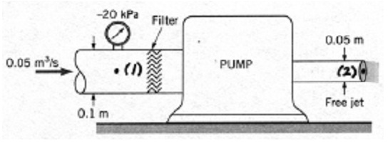
The pump illustrated in the figure adds 20 kW of power to the flowing water. The only vital loss is that which takes place across the filter at the inlet of the pump. Find out the head loss for this filter. Note that the gage pressure upstream of the filter is negative and the jet placed at the pump exit is free. Take α = 1.

738_head loss.jpg

   Related Questions in Mechanical Engineering

  • Q : P11 and P12 Pipes Explain difference

    Explain difference between the P11 and P12 Pipes?

  • Q : Excitation of Modes in Fiber A

    A multimode fiber is used to couple light into a single mode fiber. Both fibers have the same total diameter. Explain the coupling. Use equations, MATLAB, etc. if necessary. If an LED is used to excite a single mode fiber, explain the coupling of light to the fiber? U

  • Q : Change of power in flow of kinetic

    Air at 20 m/s, 260 K, 75 kPa with 5 kg/s flows into a jet engine and it flows out at 500 m/s, 800 K, 75 kPa. What is the change (power) in flow of kinetic energy?

  • Q : Aim of an airspeed indicator in aircraft

    What is the main aim of an airspeed indicator in aircraft?

  • Q : Arena Are you able to assist with these

    Are you able to assist with these two assignments in Arena simulation below? You can use the Basic Process instead of Blocks and Elements. An office of state license bureau has two types of arrivals. Individuals interested in purchasing new plates are characterized to have inter-arrival times dis

  • Q : Problem on pressure rise of a water tank

    The water level in a tank is about 20 m above the ground. A hose is joined to the bottom of the tank, and the nozzle in the end of the hose is pointed to straight up. The tank is at sea level, and the water surface is open to the environment. In the line leading from

  • Q : Lubricating oil in turbines Except the

    Except the lubrication, explain the other two functions of the lubricating oil in some of the turbines?

  • Q : Problem on displacement response time

    (i) Formulate the equation of motion for the system shown in Figure below. List two assumptions made in this formulation. (ii) Find the response of this system at t = 3s. The system begins with the displacement of 5 cm and velocity

  • Q : Problem on discharge of water In the

    In the below system, d = 6 in., D = 12 in., Δz1 = 6 ft, and Δz2 = 12 ft. The discharge of water in the given system is 10 cfs. Is the machine a turbine or a pump ? Determine the pressures at points A and B? Neglect head losses. Suppos

  • Q : Problem on turbulent flow The

    The approximate equation for the velocity distribution in a rectangular channel with the turbulent flow is 655_turbulent flow.jpg

    Discover Q & A

    Leading Solution Library
    Avail More Than 1438320 Solved problems, classrooms assignments, textbook's solutions, for quick Downloads
    No hassle, Instant Access
    Start Discovering

    18,76,764

    1929976
    Asked

    3,689

    Active Tutors

    1438320

    Questions
    Answered

    Start Excelling in your courses, Ask an Expert and get answers for your homework and assignments!!

    Submit Assignment

    ©TutorsGlobe All rights reserved 2022-2023.