--%>

Problem on degree of freedom

Draw a frequency-response curves for a damped single degree of freedom system subjected to a harmonic excitation under three different damping ratios. System has a natural frequency of ωn as the forcing frequency of the excitation is ω. Describe the relation of static and dynamic deformation responses for:
 
(i) ω/ωn << 1
(ii) ω/ωn >> 1
(iii) ω/ωn = 1

Also define whether the dynamic response is controlled by the mass, or stiffness or damping of the system for each and every case.

(b) The single degree of freedom building system is excited by a sinusoidal force as shown in figure below. Assume that the girder is rigid whereas the columns are flexible to the lateral deformation but rigid in the vertical direction. Use E = 30 GPa, I = 60 x 106 mm4 and 5 % damping and neglect the mass of columns. Find out
 
(i)  the steady state amplitude of vibration,
(ii)  the maximum shear force in the column,
(iii)  the maximum bending moment.
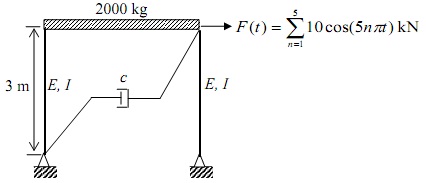
973_degree of freedom.jpg

   Related Questions in Mechanical Engineering

  • Q : Problem on mechanical efficiency of the

    The oil pump is drawing 25 kW of electric power while pumping oil with ρ = 860 kg/m3 at a rate of 0.1 m3/s. The inlet and outlet diameters of the pipe are of 8 cm and 12 cm, respectively. When the pressure rise of oil in the pump is measured to be 250 k

  • Q : Preventing the excess discharge pressure

    How we can prevent the excess discharge pressure?

  • Q : Powder Technology Explain the term

    Explain the term Powder Technology?

  • Q : Petroleum technology theories for the

    theories for the origin of petroleum, methods for detection of petroleum deposits, fractional distillation

  • Q : Solution A pump station has been

    A pump station has been designed to lift water out of a 6 metre deep pit (vented to atmosphere) via a centrifigual pump mounted at ground level. Liquid conditions 20OC Suction pipe work losses 2.0 metres NPSH safety factor 5.0 kPa Vapor pressure @ 20oC 0.25 metres (a) Calculat

  • Q : Describe Process Flow Diagram Process

    Process Flow Diagram: A Process Flow Diagram or System Flow Diagram exhibits the relationships among the main components in the system. It too has fundamental information regarding the material balance for the process.

  • Q : Define Mechanism Mechanism : The

    Mechanism: The mechanism is a system of moving parts which changes an input motion and force into the desired output force and motion.

  • Q : Difference between projectile motion

    Difference between projectile motion and rocket motion:A projectile has no motor or rocket on it, therefore all of its momentum is provided to it as it is launched. An illustration of a projectile would be pen which you throw across a room.

  • Q : Servo drive What do you mean by Servo

    What do you mean by Servo drive and how mechatronic integration approach is improved by it.

  • Q : Formation of Cavitation Explain the

    Explain the reason behind formation of the Cavitation in the Centrifugal Pump and not in the Displacement Pump?